Layer 2 Redundancy
Logical Switch
Cisco offers two approaches to building logical switches: StackWise and Virtual Switching System.
StackWise makes multiple switches act as one switch. VSS makes multiple chassis act as one chassis.
StackWise
Combines up to nine StackWise capable switches into a single virtual switch with a single management plane.
Switches collectively create a single 32Gbps or 64Gbps(StackWise+) backplane by connecting with special StackWise cables.
Master Switch Election
- Switch that is currently the master
- Switch with the highest priority value (1-15 default 1)
- Switch not using the default interface-level configuration
- Switch with higher priority software version
- IP services > IP base
- Crypto > Non-Crypto Images
- Switch with the longest uptime
- Switch with the lowest MAC address
Member Switch
Each switch in the stack is identified by its member number, which can be 1-9.
By default, a new stack member takes the lowest available member number.
A switch member number may be changed with the switch renumber command.
The switch member number identifies the member switch in the configuration (example: interface Gi3/0/17 would be GigabitEthernet port 17 on member switch 3)
Switch Provisioning
If a new switch is going to be added to the stack, you can provision it ahead of time with the switch provision command.
- Preconfigure member number
- Preconfigure switch type
- Preconfigure the interfaces associated with the switch
Compatibility
- All stack members ultimately must run the same IOS version
- Stack protocol version must be compatible
- Stack protocol software has a major and minor number
- Different major versions are not compatible at all
- Different minor versions are partially compatible. When there is a minor version mismatch, the stack master will attempt to upgrade or downgrade the IOS of the mismatched switch using auto-upgrade
show platform stack manager all
show platform stack ports
show switch
show switch detail
show switch neighbors
show switch stack-ports
show switch stack-ring activity [detail]
VSS
Configuration
VSS Active
redundancy
  mode sso

router ospf 1
  nsf

switch virtual domain 100
  switch 1 [priority 110]

interface port-channel 10
  switch virtual link 1

interface range tengigabitethernet3/1-2
  channel-group 10 mode on
  no shutdown

switch convert mode virtual
VSS Standy
redundancy
  mode sso

router ospf 1
  nsf

switch virtual domain 100
  switch 2 [priority 100]

interface port-channel 20
  switch virtual link 1

interface range tengigabitethernet3/1-2
  channel-group 20 mode on
  no shutdown

switch convert mode virtual
Router# show switch virtual
Switch mode : Virtual Switch
Virtual switch domain number : 100
Local switch number : 1
Local switch operational role: Virtual Switch Active
Peer switch number : 2
Peer switch operational role : Virtual Switch Standby
Router# show switch virtual role
Switch Switch Status Preempt Priority Role Session ID
Number Oper(Conf) Oper(Conf) Local Remote
-----------------------------------------------------------------------------------
LOCAL 1 UP FALSE(N) 110(110) ACTIVE 0 0
REMOTE 2 UP FALSE(N) 100(100) STANDBY 8158 1991
In dual-active recovery mode: No
Router# show switch virtual link
VSL Status: UP
VSL Uptime: 4 hours, 26 minutes
VSL SCP Ping: Pass OK
VSL ICC (Ping): Pass
VSL Control Link: Te 1/5/1
Route Processor Redundancy
Redundancy Mode
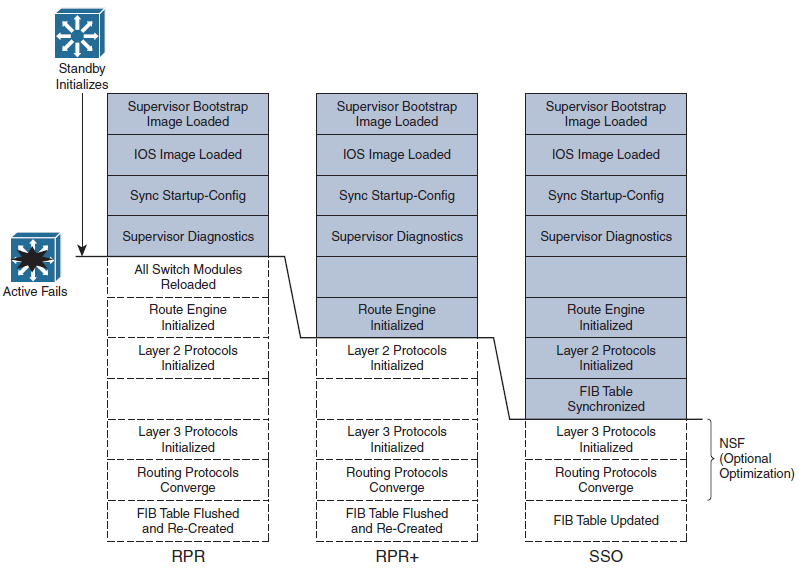
- Route processor redundancy (RPR):
The redundant supervisor is only partially booted and initialized. When the active module fails, the standby module must reload every other module in the switch and then initialize all the supervisor functions. - Route processor redundancy plus (RPR+):
The redundant supervisor is booted, allowing the supervisor and route engine to initialize. No Layer 2 or Layer 3 functions are started, however. When the active module fails, the standby module finishes initializing without reloading other switch modules. This allows switch ports to retain their state. - Stateful switchover (SSO):
The redundant supervisor is fully booted and initialized.
Both the startup and running configuration contents are synchronized between the supervisor modules. Layer 2 information is maintained on both supervisors so that hardware switching can continue during a failover. The state of the switch interfaces is also maintained on both supervisors so that links do not flap during a failover.
Comparison
Configuration
Switch(config)# redundancy
Switch(config-red)# mode { rpr | rpr-plus | sso }
If you are configuring redundancy for the first time on the switch, you must enter the previous commands on both supervisor modules. When the redundancy mode is enabled, you will make all configuration changes on the active supervisor only. The running configuration is synchronized automatically from the active to the standby module.
Show States
Switch# show redundancy states
Example
Switch# show redundancy states
       my state = 13 -ACTIVE
     peer state = 8 -STANDBY HOT
           Mode = Duplex
           Unit = Secondary

        Unit ID = 2

Redundancy Mode (Operational) = Route Processor Redundancy Plus
Redundancy Mode (Configured)  = Route Processor Redundancy Plus
     Split Mode = Disabled
   Manual Swact = Enabled
 Communications = Up

   client count = 11
 client_notification_TMR = 30000 milliseconds
          keep_alive TMR = 9000 milliseconds
        keep_alive count = 1
    keep_alive threshold = 18
           RF debug mask = 0x0
Switch#
The output above shows that the switch is using RPR+ and that the second supervisor module (denoted by unit ID 2 and “my state”) holds the active role. The other supervisor module is in the standby state and is HOT, meaning that it has initialized as far as the redundancy mode will allow.
Supervisor Synchronization
By default, the active supervisor synchronizes its startup configuration and configuration register values with the standby supervisor. You also can specify other information that should be synchronized.
Switch(config)# redundancy
Switch(config-red)# main-cpu
Switch(config-r-mc)# auto-sync { startup-config | config-register | bootvar }
Nonstop Forwarding
When there is a processor change in SSO, unlike the FIB, which is downloaded to any switch hardware that can perform CEF, the RIB needs to be rebuild. Cisco provides a feature that can reduce the time elapses, NSF.
Instead of waiting on any configured Layer 3 routing protocols to converge and rebuild the FIB, a router can use NSF to get assistance from other NSF-aware neighbors. NSF functions must be built in to the routing protocols on both the router that will need assistance and the router that will provide assistance.
NSF is supported by the Border Gateway Protocol (BGP), Enhanced Interior Gateway Routing Protocol (EIGRP), Open Shortest path First (OSPF), and Intermediate System-to- Intermediate System (IS-IS) routing protocols.
Configuration
BGP
Switch(config)# router bgp as-number
Switch(config-router)# bgp graceful-restart
EIGRP
Switch(config)# router eigrp as-number
Switch(config-router)# nsf
OSPF
Switch(config)# router ospf process-id
Switch(config-router)# nsf
IS-IS
Switch(config)# router isis [ tag ]
Switch(config-router)# nsf [ cisco | ietf ]
Switch(config-router)# nsf interval [ minutes ]
Switch(config-router)# nsf t3 {manual [ seconds ] | adjacency }
Switch(config-router)# nsf interface wait seconds